

Lunar or planetary exploration rovers have and will continue to have the function of travel across areas in unknown environments within limited mission periods. Planetary and lunar surface generally consists of flat ground, sand, and scattered rocks. The localization of lunar rovers and robots is essential for carrying out important scientific functions and data gathering on the lunar surface. The localization and navigation information can enhance the overall operations. If route planning and navigation are performed using terrestrial technologies, it will cause many problems related to the operation, and the lag will slow down the process of operations. So there is a need for a localization and navigation system which is independent of the terrestrial infrastructure. With the use of visual sensors and cameras or other kinds of sensors, this function can be performed. The lunar surface is full of caves, lava tubes, and craters, in such environments the rovers or any other autonomous robotic system may enter a difficult terrain range and may need to localize itself or navigate to a specific location. In many cases, the gathered data without any location information can be of no or very limited use.
The localization of a rover or a robot on the lunar surface involves its position and orientation within a certain frame of reference. This frame of reference can be either global or local. The global positions in previous missions were measured using radio signals from satellites refined by matching orbital images with lander’s local images using different spatial intersection techniques. The local reference system can be with respect to any landmark position. The robotic agent or rover can measure its position using different techniques like dead reckoning, sun sensing, and visual odometry.
Positioning and Navigation play a key role during autonomous operation in planetary exploration missions. It is a challenging task due to the uncertainty in the environment and limitations in communications. In this article, I discuss various technologies that can be considered for localization on the lunar surface. NASA’s Artemis program to return humans to the Moon in the 2024-2028 timeframe provides a major stimulus to design such systems, to pave the way for human exploration. Despite this high number and a wide variety of missions, there is currently no common support infrastructure in place around the Moon, which means that each individual mission must develop and transport its own means of autonomous navigation system. For the long-term continuous development on the Moon, the systems must operate reliably but also we focus on the maintenance issues and cost reduction. So systems should be designed which are easy to maintain. Even in a scenario where a dedicated navigation and positioning system is developed for the lunar surface, we still need to have a backup system, which can be used in situations where the primary system fails.
The extreme Lunar environment offers challenges in positioning and wayfinding for both people and robotic systems. The following elements impact positioning:
- Lack of magnetic field
- Craters
- Volcanic features, lava tubes
- Areas of high and low (shadow) Illumination
- No localization infrastructure
In this article, some technologies used for this purpose are discussed. These techniques will be slightly different from those used on Earth because of the absence of dedicated satellites or any other artificial landmarks. By dedicated satellites, we mean systems like GPS, GALILEO, GLONASS and BEIDOU, etc. Creating a specific Lunar GPS is a solution far down the line. NASA’s Lunar GNSS Receiver Experiment (LuGRE) project plans to use the GPS signals from earth-orbiting satellites for Lunar-based positioning. ESA’s Lunar Communication and Navigation Services (LCNS) looks at a comprehensive system of satellites and beacons for space-based Positioning, Navigation, and Timing (PNT). Positioning based on radio antennas similar to cell phone positioning or relying on long-range beacons like LORA and Ultra Wide Band are also considered. But before all these technologies can be fully launched, there would still be lunar missions that would require lightweight solutions for positioning and navigation.
The lunar exploration missions require a solution that can fulfill the needs of these missions. As we discussed above, the market needs solutions for the precise positioning of rovers and astronauts. There is a need for a system, which is standalone, and independent of any satellite system or terrestrial system. This system can be used for security and monitoring, scientific exploration, identification, path planning, and mapping. Let’s move forward and explore this area a bit.
Wheel Encoders and Dead Reckoning
Dead reckoning is a localization process where the current position is determined based on the previous position along with other parameters like its course and speed over a known interval. Dead reckoning can use wheel Odometry or Inertial Measurement Unit (IMU). But errors can be caused by issues like an improper alignment of wheels, slop in gears, or wheel slippage. This error when accumulated can significantly affect the overall process. To avoid the error dead reckoning can be combined with other methods.
Localization Using Camera
Rovers and robots are usually equipped with cameras to carry the operations and record the observations. Some agents can carry even multiple cameras, and these cameras may have wide view features, thus they can visually obtain information about their global environment. Cameras can obtain information about both far and near areas. It is also possible to view the same place from different directions, it makes this technology suitable for localization and navigation. In the case of extra-terrestrial explorations where things such as artificial landmarks, walls, etc. are absent, methodologies based on Visual Odometry (VO) are employed for localization. There is usually an error associated with each frame so this method is used in combination with dead reckoning in order to get close results to the ground truth.
Localization Using Visual Odometry
This method uses a stereo camera, which is mounted on a rover, it takes two slightly different images of the scene in front of the rover. Stereo matching is performed based on the features and the captured positions of each extracted feature. Outlier features can be extracted. When the rover moves to some distance the camera again captures stereo images and the process of feature extraction is performed. Now, this new image is projected onto the previous image based on odometry. The key concept utilized in this technique is tracking features visible to the camera and so if the features are not in significant number (like on plain surfaces), errors can get worse. The intensive image processing and computational requirements of this method can be dealt with the usage of suitable hardware and implementing intelligent algorithms.
Localization Using 3D Model of the Robot
Another methodology that can be implemented is by using a monocular camera mounted on the lander. This camera records images of the moving rover and computes similarity measurements between the image taken and a synthetic image generated by the 3D object model of the robot. This method can be used only for very short-range localization such as in the case of a mining robot which is meant to traverse short fixed paths and is very accurate.
Localization Using Camera and Satellite Images
To measure the location globally this method can be used, where the exploration agent takes panoramic images of the surrounding area and these images are correlated with stereo images taken from a satellite. This method is computationally intensive compared to Visual Odometry and 3D model similarity estimation methods hence can be employed when these methods become unreliable over large distances.
Localization Using Camera and Celestial Bodies
One more approach to a global localization mechanism in an unknown environment includes making use of a set of sun altitudes by processing a sequence of time-indexed images of the sky. On a celestial body, each altitude of the sun constraints the viewer to a circle called the circle of equal altitude. A set of such circles of equal altitude can be intersected to obtain the viewer’s position. The idea of measurement of the sun’s altitude can be generalized to other celestial bodies: satellites, planets, stars.
Star system is another technique of global localization. Comparisons are made between the celestial coordinate system (star patterns seen by planet) with horizon coordinate system (star patterns as seen by an observer on that planet). By this technique latitude, longitude, and heading of the rover can be known. A wide field of the view star tracker is used to take images of the sky directly above the rover at a precisely known time with an inclinometer reading and a quaternion is extracted which gives a vector from the center of the planet to the position of the rover from which latitude and longitude of the rover can be known and the roll of the image taken from the star tracker compared to the star pattern gives the orientation of the rover. This methodology can be implemented during night times on the planet where vision-based techniques render ineffective. But in order to implement this method, the star pattern as seen from the planet’s surface has to be known prior. The accuracy of the measurement is dependent on the resolution of the inclinometer used since the error gets multiplied by the radius of the planet while computing latitude and longitude.
Between December 1968 and December 1972, a total of nine Apollo spacecraft carried human crews away from the Earth to another heavenly body. Primary navigation for these missions was done from the ground. As a backup, and for segments of the mission where ground tracking was not practical, an onboard inertial navigation system was used. Astronauts periodically used a sextant to sight on stars and the horizons of the Earth and Moon to align the inertial system and to verify the accuracy of the Earth-based tracking data.
Localization Using Remote Viewing of a Colored Cylindrical Target
This visual approach for determining the robot’s location and orientation requires observation of a cylindrical object with a camera from a reference point. The colored cylinder is mounted on the rover or robot, and the camera attached to the lander. In its four quadrants, the cylindrical object has four distinct colors. The distance from the lander of the robot can be measured based on the apparent size of the cylinder in the camera frame. The amount of each color seen in the picture can help determine the orientation.
Wireless Sensor Networks (WSNs)
The use of wireless sensors for localization purposes is also an active research area. These wireless nodes can be used to track a point. Some methods in this area are lateration (when distances between nodes are used), angulation (when angles between nodes are used), cell proximity (a node wants to determine its position or location in the proximity of an anchor), etc. But these techniques are influenced by different environmental factors. Radio frequency has an edge over other frequencies as these show better results. Technologies like Bluetooth, Zigbee, WiFi networks come under Radio Frequency. Each technology has its own strengths and weaknesses and should be chosen depending on the application.
Localization Using WSN and Odometry
As WSNs can have a centimeter-level location precision, we can use this technology with odometry (encoders) to accurately locate a robot. For locating the robot, ZigBee’s modules based on IEEE 802.15.4 can be used that minimize the cumulative system error caused by odometry. This is performed by data fusion using Kalman Filters and Dead Reckoning techniques. When these techniques are used to locate the robot, the ambiguity in the robot location is greatly diminished.
However, when using Received Signal Strength Indicator (RSSI) measurement for wireless localization, the signal strength is susceptible to attenuation due to changes in the environment which leads to incorrect measurements. To avoid this, some methods use cameras to detect the nodes, which are equipped with infra-red LEDs.
Localization Using LF/VLF Electromagnetic Signals
A methodology using low frequency or very low frequency (LF/VLF) electromagnetic waves can be employed where perpendicular receiver antennas are mounted on the rover and the angle of arrival of the signal with respect to a pre-installed signal source with a known location is measured. Measuring such angles with respect to three or more sources can give the location of the rover by triangulation. The low-frequency nature of electromagnetic (EM) waves makes no error due to diffraction, refraction, and absorption. The only challenge that could be faced is with the installation of the signal sources in the environment.
Wireless Localization Using Radio Signal Mapping
An approach for wireless localization using Radio Signal Mapping makes use of received radio signal-strength to localize the source of the signal. Gaussian processes are used to build an online model of a signal strength map that can provide the best likelihood of the source location. Radio signal propagation is a complex process and the received power is a function of the following factors: distance from the source, shadowing due to obstacles, and multipath phenomena (due to reflections and refractions). Wireless communication protocols such as Zigbee can be considered for such localization. The RSSI field is readily available in the Zigbee datagrams indicating the strength of the received power. Received power can be modeled by Rayleigh or Rician distribution. Now, such kind of complex modeling to compensate for precision can be avoided by not choosing radio signal propagation. Instead, a sensor suite to build a location sensing network can be considered which makes use of two infra-red landmark modules and an image sensor.
LiDAR
LiDAR is widely used in applications like terrain mapping, remote sensing, contour mapping, and so on. It can have up to millimetric precision distance measurements. This LiDAR quality was applied indoors to locate the vehicles using the 3D LiDAR to acquire the isometric scene map in front of the vehicle, which is then compared to pre-existing indoor map to assess the place of the vehicle. In the case of extraterrestrial worlds, a similar methodology can be applied. In a method using LiDAR and Satellite Altimetry, a 3D LiDAR scan of the environment is taken and features such as hilltops, etc. are extracted. This feature cloud is correlated with the features from the global feature map which is obtained from a satellite-based laser altimeter by using the Data-Aligned Rigidity-Constrained Exhaustive Search (DARCES) feature matching algorithm. The outliers are removed using the RANSAC (Random Sample Consensus) method giving us the position and orientation of the rover on a global level. A global feature map can also be obtained using a high-resolution stereo camera. Position obtained using this method has GPS level accuracy but requires high computation. Hence, it can be used when local level localization methods like visual odometry are unreliable.
A similar technique can be used for the localization of rovers in long-range exploration missions. The terrain of the roving area is scanned with a LiDAR during the final descent phase of the mission.
Laser Sensors
Laser sensors may be used to achieve distance measurements up to millimeter precision. The distance spectrum that can be determined by the laser selector varies from few meters to a few kilometers. However, when you pick a laser for your use, security plays an important role. Lasers Class 1 and 2 are considered safe and are often used for robot localization in ordinary operating conditions.
A laser range finder along with an infrared (IR) camera can be used to locate a robot. The IR camera can be used to achieve the robot’s global location and orientation as regards a landmark. In relation to the robot’s current location, the laser range finder is used to build a local 2D grid map. The details from the IR signature transform this location into a global position. Using the iterative closest point algorithm and details on odometry, the optimal path is determined for reaching your destination after positioning in the global coordinate system.
The above technique can be replaced with a much better technique which uses a Time-of-Flight (ToF) camera which is faster than using a laser range finder. A ToF camera captures all the distances in the scene as opposed to point by point with the laser range finder. It also includes information about the texture, color, and intensity of the scene which makes it more preferable over a laser scanner.
Design Considerations
I have reviewed several possible technologies for localization of a robot in an extraterrestrial environment and identified the following techniques that can be considered for developing a localization system:
- Dead reckoning – Due to excessive wheel slippage on Martian soil, dead reckoning alone cannot give correct values for localization. However, when combined with other sensor techniques like Wireless, Camera, LiDAR, etc., precise localization can be achieved. Dead reckoning along with wireless sensor data (Zigbee) gives accurate localization results in an indoor environment. For extraterrestrial environments, dead reckoning can be used along with a camera or LiDAR. This technique can be used for both short-distance and long-distance traveling robots.
- Cameras – Cameras are the most promising technologies for extraterrestrial robot localization. Visual odometry using a stereo camera is the best technique that can be implemented because of its simplicity and accuracy in that range. For global level localization or long distances, the camera can be integrated with LiDAR or Satellite scans to yield GPS level accuracy. For very short distance localization, i.e., up to few tens of meters, techniques such as remote viewing of colored cylinder and localization using a 3D model of a robot can be implemented.
- Wireless Sensor Networks – Using wireless sensor networks for localization requires optimal placement of nodes in the environment which could be challenging. Wireless sensor nodes can be deployed by two methods, either by deploying them during landing or shooting away from the sources with a certain angle after the lander is on the ground. If nodes are deployed at optimum locations, wireless sensor networks can be used for precise localization. The RSSI values from the nodes can be used along with dead reckoning values to obtain the best prediction for the location of the robot when traveling short distances. Due to the limited communication range, this method cannot be used for long-distance traveling robots.
- Laser – Lasers can be used to obtain accurate distance measurements. 2D scan of the environment obtained using a laser range finder and the data from a landmark viewing camera can be used to obtain localization information for short-distance traveling robots. However, for long-distance traveling robots, advanced technologies like LiDARs and ToF cameras can be used.
- LiDAR – LiDAR with satellite imagery and altimetry gives very accurate localization on a global scale. It would require intensive computations with highly sampled and high-resolution data if this technique is to be implemented for localization at a local level, so visual odometry suits better at this level.
- The Doppler radar works on exactly the same principle as police radars and the microwave door openers at grocery stores. The reflected signal is beat against the transmitted signal, producing an audio tone whose frequency is proportional to velocity. There are three separate beams, two to the sides and one behind. Quadrature mixers are used to determine the sign of the velocity readings, i.e., whether the ground is coming or going.
The microwave signal can penetrate the lunar regolith to some depth, and it is sensitive to the regolith thermophysical parameters. Compared to the previous lunar missions, the microwave techniques have been paid more attention in recent mission, such as:
- the Lunar Radar Sounder (LRS) onboard Kaguya (formerly SELENE, for SELenological and ENgineering Explorer),
- Miniature Radio-Frequency (Mini-RF) instrument onboard Lunar Reconnaissance Orbiter (LRO), and
- the Lunar Penetrating Radar (LPR) onboard the Yutu rover in Chang’e-3 (CE-3) mission.
Path Planning and Navigation Inside Off-world Lava Tubes and Caves
Scientists and astronauts explore lunar caves, hereby mapping out the structure and collecting samples. Exploring these pits using wheeled ground robots will prove to be a daunting challenge. Many pits from NASA Lunar Reconnaissance Orbiter (LRO) images show evidence of collapsed entrances due to past geologic activity.
On Earth, many lava tubes have collapsed entrances that are extremely rugged and are only accessible by some of the fittest hikers. In addition, conventional methods of path-planning and navigation used by planetary rovers are not applicable in these pits as they are sheltered by thick rock, which blocks sunlight and prevents radio communication with the outside world. To explore such pits, the lunar rover’s capabilities should match that of a terrestrial vehicle used for similar purposes but do so in low-gravity, air-less or low-pressure environments.
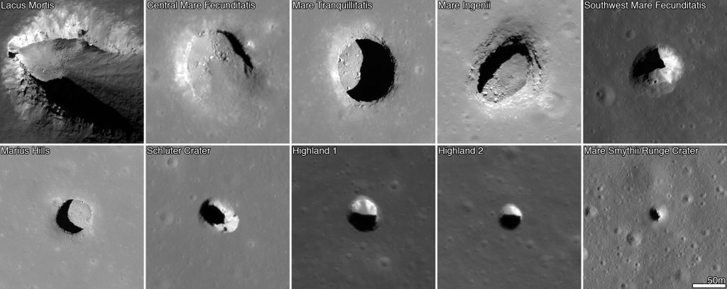
Credits: NASA/GSFC/Arizona State University
Each robot can be equipped with a 2D laser range finder mounted on a servo to enable 3D range scanning. A global frame (X, Y) is constructed with respect to the fixed robot. At any given instant, when one robot moves, its relative position, and orientation changes can be measured with respect to the neighboring stationary robots and then can be converted to the relative position (x, y) w.r.t the global frame. For example a robot i moves from its initial position to its final position. Robot i-1 measures the range and bearing angle (R, α) of Robot i w.r.t its local frame (Xi-1, Yi-1). The global position (xi, yi) and orientation φi of Robot i can then be computed w.r.t the global frame (X, Y). So, if there are ‘n’ number of robots in between Robot i and Base 1, we must perform ‘n’ transformation to compute its global position and orientation.
Another similar approach can be where a device is used, this device is attached with the astronauts and it captures the location of astronauts continuously. This capture is irrespective of any other available means of positioning, such as Lunar GPS or beacons. As astronauts proceed forward the path is collected and the cave structure is globally mapped. When samples are collected, their location is documented. This facilitates latter analysis on the prevalence of certain materials and helps to plan future sorties. This high-quality data yields higher probabilities of finding a large deposit of valuable ore or water.
Location data is shared among similar devices through a device-to-device communication mesh. Positioning information is hereby relayed to the outside of the cave to mission control.
Dead Reckoning via Sensors on the Moving Rover
Another localization method to estimate the position and azimuth of a lunar rover is by a sensor fusion technique that is an integration of the absolute position and the relative position. The absolute position is calculated by observing the Sun and the Earth, and the relative position is measured by the dead reckoning.
The rover finds its absolute position on the Moon by observing the Sun and the Earth. Here the rover is supposed to have inclinometers and a precise time clock. The rover is also supposed to have lunar orbital information. Altitudes of the Sun and the Earth are obtained from a Sun sensor and the Earth sensor on the rover, respectively. Two of three attitude angles of the rover, roll, and pitch, are obtained by inclinometers. On the other hand, the yaw angle of the rover cannot be directly measured because a magnetic sensor is not available on the Moon. Therefore, not only the position but also the yaw angle must be estimated by using the other angles, altitudes, and azimuths of the Sun and the Earth.
To reduce the position error estimated by the Sun and the Earth observation method, it is proposed that an integrated localization method with dead reckoning. Dead reckoning is effective when a robot moves in a short distance, however, position error accumulates as a robot moves further and further. Therefore, the sensor fusion techniques are introduced to obtain the precise positioning information.
ESA’s Moonlight initiative plans to make the Moon more connected and to allow better lunar communications and navigation. The aim is to encourage private companies to help create what ESA describes as a lunar constellation of satellites and base stations providing seamless connectivity back to Earth. Some of the advantages of a constellation of satellites around the Moon include helping rovers to navigate around the lunar terrain, landing spacecraft, and allow missions to land on the far side of the Moon.
NASA is also developing relay communication and navigation architecture known as LunaNet to make it easier for lunar devices to communicate with each other and with Earth. It can also be used for positioning, navigation, and timing services for orientation and velocity determination, as well as time synchronization and dissemination (the broadcast of a stable reference time which can be used by applications). These services could be used for search and rescue, surface navigation, and location tracking. Communication technology can also be used along with dead reckoning for precise position information of the rovers, by using radio waves from the communication infrastructure.
Conclusion
Positioning and localization on the lunar surface is a challenging task. There are many limitations that must be considered while designing a localization solution. There are different techniques in literature that can be used to localize a robot, device, or astronaut in an extraterrestrial environment. All techniques have their pros and cons. Decision-makers have to choose wisely when choosing a localization technique keeping its limitations in consideration. And also different applications may require different localization techniques. Until a proper navigation and positioning system is not developed for the Moon, these techniques can serve the purpose and prove as a low-cost solution. Localization techniques like LiDAR, Radar, dead reckoning, visual odometry, Camera, or Wireless Sensor Networks are some of the techniques which can be used. There is still a lot to discover when it comes to positioning on the Moon, fusion of different techniques or multiple sensors may provide better precision and accuracy.